Chemical Etching Lead-Calcium Battery Grids Animation
The Corrosion Challenge
In the world of lead-acid batteries, grid corrosion remains the single most significant factor limiting service life. Whether deployed in uninterruptible power supplies (UPS), telecommunications backup systems, or renewable energy storage installations, batteries are expected to deliver reliable performance for a decade or more. Yet traditional grid manufacturing methods often introduce the very defects that accelerate failure.
This article explores how chemical etching transforms lead-calcium battery grid production, addressing three fundamental questions:
- What are durable battery grids, and why do they matter?
- Why is chemical etching the superior manufacturing method?
- How does the process achieve exceptional corrosion resistance?
Understanding Durable Battery Grids
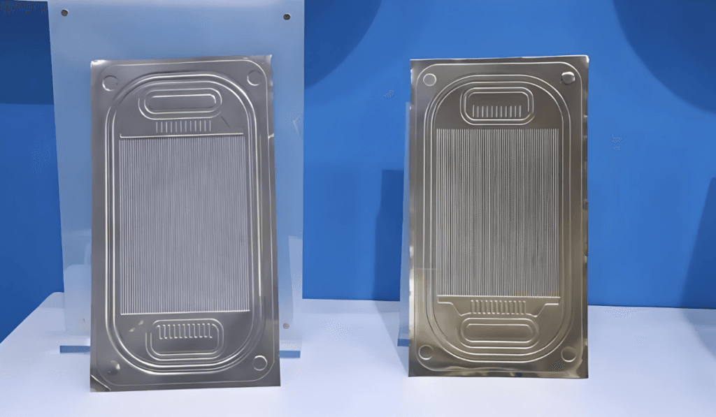
A battery grid serves as the structural backbone and current collector within a lead-acid battery plate. It performs two critical functions: it supports the active material (lead dioxide or sponge lead) that stores electrochemical energy, and it conducts current between the external terminals and the active material.
Durable battery grids are defined by their ability to resist corrosion, maintain mechanical integrity, and sustain electrical conductivity throughout an extended service life—typically 10 years or more for stationary applications. The chemistry of the grid alloy directly determines how well the battery will cycle, how long it will last, and how much maintenance it requires.
Lead-calcium alloys have become the industry standard for maintenance-free and valve-regulated lead-acid (VRLA) batteries. According to Battery University, compared to traditional lead-antimony alloys, lead-calcium offers:
- Reduced water consumption (minimal gassing during charge)
- Superior corrosion resistance in float service applications
- Lower self-discharge rates
However, the manufacturing method used to shape these alloys into grid structures profoundly affects their ultimate corrosion performance. Cast grids often suffer from irregular grain structures and weak grain boundaries that accelerate corrosion. Wrought (mechanically formed) grids can introduce residual stresses and microcracks that become initiation sites for corrosion attack.
Why Chemical Etching?
The central question facing battery engineers is this: given the critical importance of grid integrity, what manufacturing method delivers the highest corrosion resistance?
The Problem with Traditional Methods
Casting—the dominant method for decades—involves pouring molten lead-calcium alloy into metal molds. While cost-effective for simple geometries, casting introduces:
- Porosity and inclusions from the solidification process
- Inconsistent grain structures that vary across the grid
- Surface irregularities that concentrate electrochemical attack
Stamping and expanding—where a continuous cast strip is slit and stretched to form grid patterns—eliminates some casting defects but introduces mechanical stress. Research from the Advanced Lead-Acid Battery Consortium indicates that residual stresses from mechanical forming can lead to accelerated grain-boundary corrosion, particularly on the positive plate where electrochemical attack is most aggressive.
The Chemical Etching Advantage
Chemical etching (also known as photochemical machining or chemical milling) offers a fundamentally different approach. Rather than shaping metal through heat or mechanical force, etching dissolves unwanted material using precisely controlled chemical reactions. This yields several corrosion-resistant advantages:
| Attribute | Chemical Etching Benefit |
|---|---|
| Stress-Free Processing | No mechanical deformation preserves the alloy’s inherent anti-corrosion properties |
| Ultra-Smooth Surfaces | Eliminates micro-crevices that serve as corrosion initiation sites |
| Uniform Geometry | Optimized rib profiles reduce current-density hotspots that accelerate corrosion |
| Alloy Integrity | No heat-affected zone or grain structure alteration |
| Dimensional Accuracy | Achieves tolerance of ±0.01 mm for consistent grid geometry |
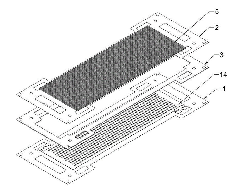
The Manufacturing Process: Step-by-Step Equipment and Function
The production of chemically etched lead-calcium battery grids follows a continuous coil-to-coil process. Below is a detailed breakdown of each stage, including the specific equipment involved and its role in achieving high corrosion resistance.
Step 1: Material Unwinding & Surface Preparation
Equipment: Pay-Off Reel, Alkaline Cleaning Station, Micro-Etching Unit
The process begins with a coil of lead-calcium alloy strip—typically Pb-Ca-Sn-Al compositions with calcium content ranging from 0.04% to 0.1%. The strip thickness for battery grid applications generally falls within 0.25 mm to 0.50 mm, though specialized designs can utilize the broader 0.05–0.3 mm range.
The pay-off reel maintains consistent tension as the strip enters the cleaning line. In the alkaline cleaning station, heated solutions remove rolling oils, oxides, and surface contaminants. This step is critical: any residue compromises photoresist adhesion, leading to pattern defects that could create localized corrosion points.
The micro-etching unit then creates a controlled surface roughness (approximately 0.5–1.0 μm Ra) using a mild acidic solution. This mechanical anchoring surface significantly improves the bond between the lead-calcium substrate and the subsequent photoresist layer.
Step 2: Photoresist Application
Equipment: Dry Film Laminator (Class 1000 Cleanroom Environment)
A dry film laminator applies a photosensitive polymer film to both sides of the lead-calcium strip. This operation occurs within a cleanroom to prevent airborne particles from causing pinhole defects—particularly important for maintaining grid integrity where corrosion resistance demands flawless surface coverage.
The laminator uses heated rollers (typically 100–120°C) to apply uniform pressure, ensuring complete adhesion without entrapping air bubbles. The photoresist thickness is carefully selected based on the required etch depth, which directly influences the final grid profile.
Step 3: UV Exposure (Pattern Transfer)
Equipment: Double-Sided Contact Exposure Unit
The laminated strip enters a double-sided UV exposure unit, where it is precisely aligned between two high-resolution glass phototools. These phototools contain the negative image of the desired grid pattern—including optimized rib geometries and open-area distributions designed to minimize current-density hotspots that accelerate localized corrosion.
High-intensity UV light (typically 365 nm or 405 nm) passes through the transparent areas of the phototool, polymerizing (hardening) the photoresist in those regions. The unexposed areas remain soft and will be removed in the developing stage. Alignment accuracy is critical for maintaining symmetrical etch profiles on both sides of the strip.
Step 4: Developing
Equipment: Spray Developer Chamber
The strip enters a spray developer chamber where a dilute alkaline solution (typically sodium carbonate) is applied through oscillating spray nozzles. This solution dissolves the unexposed (non-polymerized) photoresist, revealing bare lead-calcium in the areas intended for removal—the open spaces of the grid pattern.
The development process is precisely timed and temperature-controlled to ensure complete removal without attacking the polymerized mask. Over-development can erode fine feature edges, while under-development leaves residual resist that blocks etchant access, creating incomplete grid openings.
Step 5: Chemical Etching
Equipment: Conveyorized Spray Etcher with Oscillating Nozzles
This is the core of the manufacturing process. The strip travels through a conveyorized spray etcher—a multi-chamber system where heated etchant is sprayed onto both surfaces through high-pressure oscillating nozzles. For lead-calcium alloys, the etchant is typically a proprietary formulation of fluoroboric acid or other lead-compatible chemistry designed to achieve clean dissolution without forming insoluble byproducts.
The etching parameters are carefully controlled:
- Etchant temperature: 45–55°C
- Nozzle pressure: 20–40 psi
- Conveyor speed: Adjustable to achieve desired etch depth
Because the process dissolves material from both sides simultaneously, it produces a symmetrical grid profile with smooth, tapered sidewalls. This uniformity is essential for corrosion resistance—sharp corners or stress concentrators are eliminated. The process consistently achieves tolerance of ±0.01 mm across the entire grid geometry.
Step 6: Resist Stripping & Finishing
Equipment: Caustic Stripper Station, Cascade Rinse System, Air Knife Dryer
After etching, the now-revealed lead-calcium grid passes through a caustic stripper station (sodium hydroxide or proprietary stripper chemistry) that removes the hardened photoresist. The strip then moves through a cascade rinse system using deionized water to eliminate all residual chemicals—a crucial step for surface quality and subsequent active material adhesion.
Finally, air knives blow heated, filtered air across the strip to remove moisture, producing a clean, dry grid ready for the pasting operation where active material is applied. The resulting grid exhibits no burrs, no residual stress, and a uniform surface that maximizes corrosion resistance.
Key Process Parameters
| Parameter | Specification |
|---|---|
| Material Thickness | 0.05 – 0.3 mm (expandable to 0.50 mm for industrial batteries) |
| Dimensional Tolerance | ±0.01 mm |
| Typical Alloys | Pb-Ca-Sn-Al (0.04–0.10% Ca) |
| Etching Method | Dual-sided spray etching |
| Surface Finish | Stress-free, burr-free, uniform grain structure |
| Corrosion Resistance | Enhanced vs. cast or stamped alternatives |
Process Comparison: Chemical Etching vs. Laser Cutting
When evaluating manufacturing methods for lead-calcium battery grids, engineers must consider not only cost and throughput but also the metallurgical impact on corrosion performance. While laser cutting offers flexibility for prototyping, chemical etching provides distinct advantages for production-grade corrosion resistance.
| Factor | Chemical Etching | Laser Cutting |
|---|---|---|
| Heat-Affected Zone | None—room temperature process | Significant HAZ alters grain structure at cut edges |
| Residual Stress | Zero mechanical or thermal stress | Thermal stress from localized melting |
| Corrosion Risk | Minimal—original alloy structure preserved | HAZ creates preferential corrosion sites |
| Surface Finish | Smooth, tapered edges | Recast layer with micro-cracks |
| Material Compatibility | Excellent for lead alloys | Lead’s high reflectivity and thermal conductivity reduce efficiency |
| Throughput | Continuous coil processing; high volume | Serial process; slower for large-area grids |
| Feature Resolution | ±0.01 mm achievable | ±0.025 mm typical for lead alloys |
For lead-calcium grids, the absence of a heat-affected zone in chemically etched parts is perhaps the most significant advantage. Laser cutting, by contrast, melts and vaporizes material, creating a recast layer with altered metallurgy that corrodes preferentially during battery operation.
Applications: Where Durable Battery Grids Deliver Value
Chemically etched lead-calcium battery grids are deployed across industries where reliability, longevity, and maintenance-free operation are paramount. Below are specific applications with precise details on where these components are utilized.
Telecommunications Backup Power
Telecommunications towers and data centers require battery strings that provide uninterrupted power during grid outages. Etched lead-calcium grids are found in:
- VRLA Battery Racks: 48V strings powering base station equipment, with grids designed for 10+ year float life.
- Central Office Backup: Large-format 2V cells (1000–4000 Ah) where grid integrity directly determines system reliability.
These batteries are integrated into DC power systems from manufacturers such as Vertiv, Eaton, and Delta Electronics, installed in telecom shelters and data center UPS rooms.
Uninterruptible Power Supplies (UPS)
From hospital operating rooms to industrial control systems, UPS systems depend on battery strings that perform when called upon:
- Modular UPS Systems: 12V monoblocs with etched grids providing consistent performance across the entire battery string.
- High-Power UPS: Large 12V and 2V cells used in data centers and manufacturing facilities, where a single grid failure can cause costly downtime.
In these applications, the batteries are housed within UPS enclosures from Schneider Electric (APC), Eaton, and Socomec, serving as the critical energy storage component.
Renewable Energy Storage
Solar and wind installations increasingly rely on battery storage for grid stabilization and time-shifting:
- Off-Grid Solar Systems: Battery banks using deep-cycle VRLA batteries with corrosion-resistant grids, deployed in remote telecommunications, rural electrification, and residential solar installations.
- Grid-Scale Storage: Large 2V cells assembled into containerized energy storage systems (ESS), where thousands of grids must perform reliably for 15+ year project lifespans.
These systems integrate with inverters from SMA, Fronius, and Tesla Energy, forming the backbone of distributed energy storage infrastructure.
Motive Power & Industrial Vehicles
Forklifts, automated guided vehicles (AGVs), and airport ground support equipment utilize lead-calcium batteries for opportunity charging applications:
- Forklift Batteries: 24V to 80V traction batteries where grid durability determines usable cycle life in demanding industrial environments.
- AGV Power Packs: Sealed batteries with etched grids providing consistent performance across warehouse automation systems.
These batteries are manufactured by industrial battery specialists such as EnerSys, Exide Technologies, and Crown Battery, installed in material handling equipment from Crown, Toyota, and Hyster-Yale.
Chemical etching machine