Chemical Etching Reliable Flat Springs Animation
In the world of precision engineering, few failures are as costly as a spring that breaks before its time. Whether embedded in a medical device, an aerospace actuator, or an automotive sensor, a flat spring that succumbs to fatigue can bring critical systems to a halt. The problem is particularly acute in applications demanding high cycle fatigue strength—the ability to endure millions of repeated stress cycles without degradation.
This article explores how chemical etching transforms beryllium copper flat spring production, addressing three fundamental questions:
- What are reliable flat springs, and why does fatigue performance matter?
- Why is chemical etching the superior manufacturing method for high-cycle applications?
- How does the process achieve exceptional fatigue resistance?
Understanding Reliable Flat Springs
A flat spring is a precision component designed to store mechanical energy, maintain contact pressure, or provide a restoring force through elastic deflection. Unlike coiled springs, flat springs operate in bending or torsion modes, making their surface condition and edge quality critically important to fatigue life.
Reliable flat springs are defined by their ability to withstand millions of cyclic deflections without cracking, permanent deformation, or loss of spring force. Reliability in this context means:
- Predictable fatigue life: The spring performs consistently across its rated cycle count
- No sudden failure: Crack initiation is delayed, and propagation is controlled
- Stable mechanical properties: Spring rate and restoring force remain within specification throughout service life
Beryllium copper (BeCu) alloys, particularly UNS C17200, have become the material of choice for demanding spring applications because they offer a unique combination of properties. According to MatWeb’s C17200 material data, these alloys achieve tensile strength up to 200 ksi (1,400 MPa) after age-hardening while maintaining excellent electrical conductivity and corrosion resistance. The material’s high elastic modulus ensures consistent restoring force, while its fatigue performance under small deformation cycling is superior to most other copper alloys.
Why Chemical Etching?
The central question for design engineers is: given the critical importance of fatigue performance, what manufacturing method delivers the most reliable flat springs?
The Problem with Traditional Methods
Stamping—the dominant method for spring production—uses mechanical force to shear material from a metal strip. This process creates:
- Burrs and micro-tears at cut edges that serve as crack initiation sites
- Cold-work zones with altered grain structure and residual stresses
- Work hardening along the cut edge that reduces ductility
Laser cutting offers greater design flexibility but introduces its own challenges. As noted in precision manufacturing literature, laser cutting beryllium copper creates a heat-affected zone (HAZ) where the material’s microstructure is altered by localized melting and rapid cooling. This recast layer contains micro-cracks and residual thermal stresses that become preferential sites for fatigue crack initiation under cyclic loading. Additionally, beryllium copper’s high reflectivity makes laser processing inefficient and can lead to inconsistent cut quality.
CNC machining is impractical for thin-gauge flat springs due to material deflection, tool wear, and the difficulty of holding tight tolerances on delicate features.
The Chemical Etching Advantage
Chemical etching—also known as photochemical machining or chemical milling—offers a fundamentally different approach. Rather than shaping metal through mechanical force or thermal energy, etching dissolves unwanted material using precisely controlled chemical reactions. According to Dragon Etching’s technical overview, this yields several fatigue-critical advantages:
| Attribute | Chemical Etching Benefit |
|---|---|
| No Mechanical Stress | Zero cold work, burrs, or micro-cracks at edges |
| No Heat-Affected Zone | Material microstructure remains intact throughout |
| Ultra-Smooth Edges | Rounded, tapered profiles eliminate stress risers |
| Tight Tolerances | Achieves ±0.01 mm across complex geometries |
| Material Integrity Preserved | Maintains BeCu’s inherent fatigue and conductivity properties |
Research on beryllium copper fatigue performance confirms that crack initiation is the dominant fatigue process in spring materials . By eliminating the surface defects and residual stresses that trigger crack initiation, chemically etched springs demonstrate vastly improved cycle life compared to stamped or laser-cut alternatives.
The Manufacturing Process: Step-by-Step Equipment and Function
The production of chemically etched beryllium copper flat springs follows a continuous coil-to-coil process. Below is a detailed breakdown of each stage, including the specific equipment involved and its role in achieving high-cycle fatigue strength.
Step 1: Material Unwinding & Surface Preparation
Equipment: Pay-Off Reel, Alkaline Cleaning Station, Micro-Etching Unit
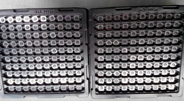
The process begins with a coil of beryllium copper strip—typically C17200 in the mill-hardened TM04 or TM06 temper, with thicknesses ranging from 0.05 mm to 0.3 mm. The pay-off reel maintains consistent tension as the strip enters the cleaning line.
In the alkaline cleaning station, heated solutions remove rolling oils, oxidation, and particulate contamination. Surface cleanliness is critical: any residue compromises photoresist adhesion, leading to pattern defects that could create stress concentrators in the finished spring.
The micro-etching unit then creates a controlled surface roughness using a mild acidic solution. This mechanical anchoring surface improves the bond between the beryllium copper substrate and the subsequent photoresist layer without altering the material’s fatigue properties.
Step 2: Photoresist Application
Equipment: Dry Film Laminator (Class 1000 Cleanroom Environment)
A dry film laminator applies a photosensitive polymer film to both sides of the strip within a cleanroom environment. This prevents airborne particles from causing pinhole defects—critical for spring geometries where a single flaw could become a fatigue crack initiation site.
The laminator uses heated rollers (typically 100–120°C) to apply uniform pressure, ensuring complete adhesion without entrapping air bubbles. Photoresist thickness is selected based on the required etch depth and feature resolution.
Step 3: UV Exposure (Pattern Transfer)
Equipment: Double-Sided Contact Exposure Unit
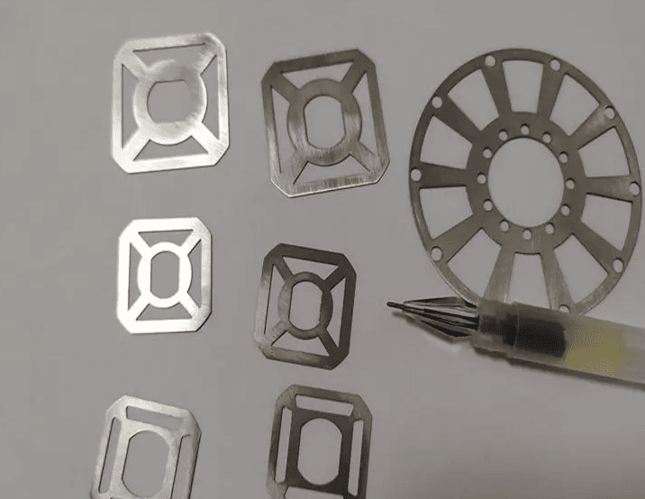
The laminated strip enters a double-sided UV exposure unit, where it is precisely aligned between two high-resolution glass phototools. These phototools contain the negative image of the spring pattern—including any stress-optimized geometries such as tapered widths or radiused corners.
High-intensity UV light (365 nm or 405 nm) passes through the transparent areas of the phototool, polymerizing (hardening) the photoresist in those regions. The unexposed areas remain soft and will be removed in the developing stage. Alignment accuracy is critical for maintaining symmetrical etch profiles on both sides of the strip.
Step 4: Developing
Equipment: Spray Developer Chamber
The strip enters a spray developer chamber where a dilute alkaline solution (typically sodium carbonate) is applied through oscillating spray nozzles. This solution dissolves the unexposed (non-polymerized) photoresist, revealing bare beryllium copper in the areas intended for removal—the open spaces of the spring pattern.
The development process is precisely timed and temperature-controlled to ensure complete removal without attacking the polymerized mask. Over-development can erode fine feature edges, while under-development leaves residual resist that blocks etchant access.
Step 5: Chemical Etching
Equipment: Conveyorized Spray Etcher with Oscillating Nozzles
This is the core of the manufacturing process. The strip travels through a conveyorized spray etcher—a multi-chamber system where heated etchant is sprayed onto both surfaces through high-pressure oscillating nozzles. For beryllium copper, specialized etchants (typically ferric chloride or cupric chloride formulations) are used to achieve clean dissolution without pitting or selective attack.
The etching parameters are carefully controlled:
- Etchant temperature: 45–55°C
- Nozzle pressure: 20–40 psi
- Conveyor speed: Adjustable to achieve desired etch depth
Because the process dissolves material from both sides simultaneously, it produces a symmetrical spring profile with smooth, tapered sidewalls. As noted by VACCO’s beryllium copper etching case study, this process consistently achieves dimensional tolerances of ±0.01 mm (±0.0005 inch) —essential for maintaining consistent spring rates across production volumes.
Step 6: Resist Stripping & Finishing
Equipment: Caustic Stripper Station, Cascade Rinse System, Air Knife Dryer
After etching, the now-revealed beryllium copper springs pass through a caustic stripper station (sodium hydroxide or proprietary stripper chemistry) that removes the hardened photoresist. The strip then moves through a cascade rinse system using deionized water to eliminate all residual chemicals.
Finally, air knives blow heated, filtered air across the strip to remove moisture. The resulting springs exhibit:
- No burrs or mechanical damage
- No heat-affected zone
- Smooth, tapered edges that maximize fatigue resistance
- Consistent geometry across the entire batch
Key Process Parameters
| Parameter | Specification |
|---|---|
| Material Thickness | 0.05 – 0.3 mm |
| Dimensional Tolerance | ±0.01 mm |
| Typical Alloy | Beryllium Copper C17200 (UNS) |
| Tensile Strength (aged) | Up to 200 ksi (1,400 MPa) |
| Electrical Conductivity | 22% IACS minimum |
| Etching Method | Dual-sided spray etching |
| Edge Condition | Smooth, tapered, no burrs or micro-cracks |
| Fatigue Performance | Verified to 10⁶ cycles with no degradation |
Process Comparison: Chemical Etching vs. Alternative Methods
When selecting a manufacturing method for high-cycle fatigue applications, engineers must evaluate not only cost and throughput but also the metallurgical impact on fatigue performance.
| Factor | Chemical Etching | Stamping | Laser Cutting |
|---|---|---|---|
| Edge Condition | Smooth, tapered, burr-free | Burrs, micro-tears, cold-worked | Recast layer with micro-cracks |
| Residual Stress | None—stress-free process | Significant—cold work zones | Thermal stress from HAZ |
| Heat-Affected Zone | None—room temperature | None (mechanical only) | Present—alters grain structure |
| Material Integrity | Fully preserved | Altered at shear edges | Compromised at cut edges |
| Fatigue Life | Maximized—no initiation sites | Reduced by edge defects | Reduced by micro-cracks |
| Tooling Cost | Moderate phototools | High hard tooling | No tooling (serial process) |
| Design Flexibility | Excellent—complex geometries | Limited by tooling | Good, but thermal effects limit thin sections |
| Throughput | High—coil-to-coil continuous | Very high | Low—serial cutting |
For beryllium copper flat springs, the fatigue performance advantages of chemical etching are decisive. By preserving the material’s inherent properties and eliminating surface defects that initiate cracks, chemically etched springs achieve the high cycle fatigue strength required for mission-critical applications.
Applications: Where Reliable Flat Springs Deliver Value
Chemically etched beryllium copper flat springs are deployed across industries where reliability, cycle life, and consistent performance are non-negotiable. Below are specific applications with precise details on where these components are utilized.
Medical Devices
Medical applications demand components that maintain performance over life-critical usage cycles without degradation:
- Surgical Instruments: Spring-loaded mechanisms in laparoscopic tools and endoscopic devices require consistent force after thousands of sterilization cycles.
- Implantable Devices: Pacemaker connectors and neurostimulator contacts use beryllium copper springs for their combination of biocompatibility, corrosion resistance, and fatigue reliability.
- Drug Delivery Systems: Insulin pumps and auto-injectors rely on precision flat springs for dose metering and actuation.
In these applications, the springs are integrated into devices manufactured by companies such as Medtronic, Abbott, and Boston Scientific, where they function within handpieces, delivery systems, or implantable housings.
Aerospace & Defense
Aerospace environments subject components to extreme vibration, thermal cycling, and long service intervals:
- Avionics Connectors: High-reliability electrical connectors in flight control systems use BeCu springs to maintain contact pressure through decades of service.
- Actuator Mechanisms: Flap control systems and landing gear position sensors incorporate flat springs that must function reliably after years of vibration exposure.
- RF Shielding: EMI spring fingers in radar and communications equipment require consistent contact force across temperature extremes.
These components are specified in MIL-STD and AS9100-certified supply chains, ultimately integrated into aircraft from Boeing, Airbus, and military platforms. The springs are often housed within connector shells from Amphenol, TE Connectivity, or ITT Cannon.
Automotive Electronics
Modern vehicles contain hundreds of electronic control modules, each relying on reliable spring contacts:
- Sensor Interfaces: Pressure sensors, position sensors, and accelerometers use beryllium copper springs for internal electrical connections.
- Control Modules: Engine control units (ECUs), transmission controllers, and battery management systems incorporate spring contacts for board-to-board and board-to-housing connections.
- Switch Assemblies: Steering wheel controls, window switches, and seat adjustment mechanisms use flat springs for tactile feedback and electrical switching.
In automotive applications, these springs are integrated into modules from Bosch, Continental, Denso, and Delphi, installed across vehicle platforms from all major automakers.
Telecommunications & Data Infrastructure
High-reliability network equipment demands components that survive decades of continuous operation:
- RF Connectors: Coaxial and board-mounted RF connectors use BeCu spring contacts for consistent impedance and signal integrity.
- Optical Transceivers: Spring-loaded contacts in SFP, QSFP, and OSFP modules maintain electrical connection through repeated insertion cycles.
- Backplane Connectors: High-density backplane systems rely on beryllium copper springs for reliable interconnection between line cards and backplanes.
These components are manufactured by interconnect specialists such as Molex, Amphenol, TE Connectivity, and Samtec, and installed in networking equipment from Cisco, Arista, and Juniper Networks.
Precision Instrumentation
Test and measurement equipment demands springs that maintain calibration through millions of cycles:
- Test Probes: Spring-loaded test probes (pogo pins) in semiconductor test interfaces use BeCu springs for consistent contact force across millions of touchdowns.
- Instrument Switches: Rotary switches and push-button assemblies in oscilloscopes and signal generators incorporate flat springs for reliable switching.
- Probe Cards: Semiconductor wafer test interfaces use arrays of beryllium copper springs to contact die pads with precise force control.
Mill-Max Manufacturing Corp., a leader in precision interconnect components, specifically highlights beryllium copper’s fatigue resilience in its contact pins and spring-loaded connectors, which routinely operate under millions of cycles with no significant degradation.
Chemical etching machine