Chemical Etching Motor Laminations Animation
In modern motor design—especially EV drives, servo systems, and high-frequency applications—the challenge is no longer just shaping metal. It’s about preserving magnetic performance while achieving ultra-high precision. This is where chemical etching of silicon steel motor laminations becomes a game-changing manufacturing method.
What Are Chemical Etching Motor Laminations?
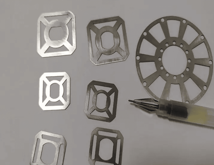
Chemical etching motor laminations are thin silicon steel sheets that are patterned using photochemical machining (PCM) instead of mechanical cutting.
Instead of stamping or laser cutting, the process uses photoresist + chemical dissolution to selectively remove material and form precise motor core geometries.
Key Characteristics
- Tolerance: ±0.01 mm
- Thickness range: 0.05–0.3 mm
- No burrs, no mechanical stress
- High design flexibility (complex slot geometries)
These laminations are stacked to form stator and rotor cores, which are essential for controlling magnetic flux in motors.
Why Use Chemical Etching for Motor Laminations?
1. Core Loss Reduction Starts with Material Integrity
Silicon steel is widely used because it naturally reduces hysteresis and eddy current losses, improving efficiency and lowering heat generation
However, manufacturing damage can destroy these advantages.
- Mechanical stamping → introduces stress and deformation
- Laser cutting → creates heat-affected zones
- Both → distort magnetic domains → increase core loss
Chemical etching avoids all of these.
According to industry studies, non-contact etching eliminates thermal and mechanical stress, preserving magnetic properties and improving consistency
2. Non-Contact Process = Ultra-Low Core Loss
Chemical etching:
- No cutting force
- No thermal input
- No grain boundary deformation
This means:
- Magnetic domains remain intact
- Eddy current paths are minimized
- Edge quality is extremely clean
In advanced applications, this can lead to:
- >30% core loss reduction vs. stamping
- Lower operating temperatures
- Longer motor lifespan
3. Precision Enables Next-Gen Motor Design
Unlike tooling-based processes, etching uses photomasks, enabling:
- Micro-slot structures
- Skewed stator teeth
- Complex flux paths
This is critical for:
- High-speed motors
- Noise reduction
- Torque ripple control
Core Manufacturing Process (Integrated Optimized Flow)
Below is the standard industrial process for chemical etching silicon steel laminations, optimized for clarity and engineering accuracy:
1. Silicon Steel Pre-Treatment
- Material: non-oriented / grain-oriented silicon steel (0.1–0.5 mm)
- Process: degreasing → pickling → DI rinse → drying
- Purpose: improve adhesion and remove oxides
2. Photoresist Coating
- Apply UV-sensitive dry film or liquid resist (5–15 μm)
- Pre-bake at 80–100°C
3. Photolithographic Exposure
- CAD pattern → photomask (glass/film)
- Vacuum lamination (0.3–0.5 MPa)
- UV exposure hardens patterned regions
4. Development
- 1–2% Na₂CO₃ removes unexposed resist
- Clean metal areas exposed for etching
5. Etching (Critical Step)
- Etchant: HF + HNO₃ + water
- Temperature: 40–60°C
- Time: 2–10 min
Result:
- Smooth, burr-free edges
- Stress-free sidewalls
- Preserved magnetic domains
6. Stripping
- Remove resist using NaOH or stripping agents
- Full cleaning
7. Post-Treatment
- Insulation layer (1–3 μm) → reduces eddy currents
- Optional annealing (<700°C) → restores magnetic properties
8. Inspection
- Dimensional tolerance: ±0.01 mm
- Core loss testing (e.g., <3 W/kg at 1.5T / 50Hz)
- Surface: no burrs, no defects
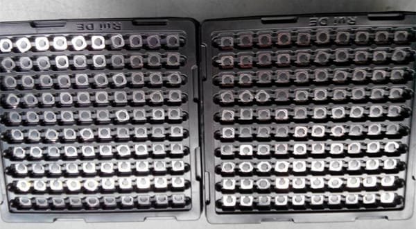
9. Lamination & Insulation
- Stack laminations
- Bond / weld / rivet
- Interlaminar resistance >10⁶ Ω·cm
10. Final Core Assembly
- Stator and rotor cores ready for motor integration
Process Comparison: Chemical Etching vs. Other Methods
| Parameter | Chemical Etching | Laser Cutting | Stamping |
|---|---|---|---|
| Precision | ±0.01 mm | ±0.02–0.05 mm | ±0.05–0.1 mm |
| Edge Quality | Burr-free | Slight melt/burr | Burrs common |
| Thermal Effect | None | High | None |
| Mechanical Stress | None | Low | High |
| Tooling Cost | Low | Medium | High |
| Core Loss Impact | Lowest | Medium | Highest |
Key Insight:
- Laser can reduce core loss via domain refinement (~16.8% improvement) but still introduces thermal effects
- Stamping is fast but damages magnetic performance significantly
- Chemical etching = best balance of precision + magnetic integrity
Key Technical Data Summary
| Parameter | Value |
|---|---|
| Thickness Range | 0.05–0.3 mm |
| Typical Material | Silicon Steel (2–4% Si) |
| Tolerance | ±0.01 mm |
| Core Loss (Example) | <3 W/kg @ 1.5T / 50Hz |
| Etching Temperature | 40–60°C |
| Etching Time | 2–10 min |
Where are chemical-etched motor laminations used?
1. Electric Vehicles (EV Traction Motors)
- High-speed permanent magnet motors
- Requirement: >96% efficiency
- Benefit: reduced heat, extended driving range
2. Servo Motors & Robotics
- Application: CNC machines, robotic arms
- Key need: low torque ripple + precision control
- Etching enables optimized magnetic paths
3. Aerospace Actuation Systems
- Flight control actuators
- Requirement: lightweight + low thermal rise
- Etched laminations reduce stress and weight
4. High-Frequency Motors (Inverters & Compressors)
- HVAC inverter compressors
- Industrial high-speed drives
- Benefit: stable operation at high frequency
5. Medical & Precision Equipment
- MRI auxiliary motors
- Surgical robotics
- Micro motors requiring ultra-thin laminations
Chemical etching machine