Optical Encoder Accuracy: The Science Behind Chemically Milled Gratings
Target Audience: R&D Engineers & Designers
Service Link: Chemical milling Service
Introduction
In high-performance motion control and measurement systems, optical encoder accuracy directly dictates machine repeatability, throughput, and product quality. When you need sub‑micron precision at high rotational speeds, chemically milled gratings—produced through a specialized Chemical milling Service—offer unparalleled edge definition, thermal stability, and signal integrity.
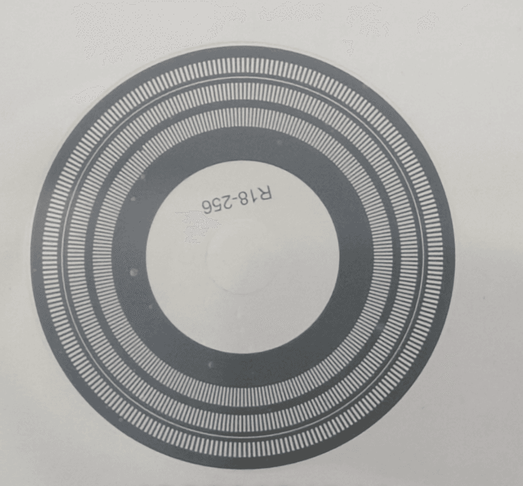
Physics of Light Interruption
An optical encoder interprets motion by shining a light through a grating and counting interruptions. The groove geometry must be controlled to within ± 5 μm to preserve code resolution and signal clarity.

- Groove depth affects light intensity contrast; too shallow yields low modulation, too deep introduces reflections.
- Channel width tolerance (< 2 μm variation) ensures consistent duty cycle and minimal jitter.
- Angular alignment errors as small as 0.1° can cause measurable phase shifts at high RPMs.
“Encoder accuracy is only as good as the grating quality. Microscopic deviations in groove geometry cause significant errors.” — Renishaw Technical Bulletin, 2023
Edge Definition: Milling vs. Alternatives
| Process | Edge Sharpness | Angular Error | Thermal Impact | Use Case |
|---|---|---|---|---|
| Laser Ablation | Good (recast edges) | 0.2°–0.5° | Heat‑affected zones | Rapid prototyping |
| Mechanical Micromachining | Excellent (tool stress) | < 0.1° | Tool‑induced stress | Low‑volume precision |
| Chemical Milling | Ultra‑sharp, burr‑free | < 0.1° | No thermal stress | High‑volume, high‑precision |

Material Matters: 316L vs. 17‑4PH Stainless Steel
| Property | 316L (Austenitic) | 17‑4PH (Martensitic) |
|---|---|---|
| Thermal Expansion | 16 × 10⁻⁶ /K | 10 × 10⁻⁶ /K |
| Yield Strength | 170 MPa | 1,100 MPa |
| Corrosion Resistance | Excellent* | Good |
| RPM Capability | Up to 20,000 | Up to 25,000 |
*Post‑etch passivation enhances 316L’s corrosion resistance for aggressive environments.
Signal Integrity Metrics
R&D teams evaluate:
- Jitter (ps) – pulse timing deviation
- Harmonic Distortion (%) – unwanted frequency components
- SNR (dB) – valid signal vs. noise floor
Testing Protocol: Spin at 5 k, 10 k, 15 k RPM, capture signals with a 1 GHz photodetector & oscilloscope, analyze edge steepness and baseline wander.
“Chemical milling reduces jitter by up to 30% and harmonic distortion by 25% compared to laser‑ablated gratings.” — IEEE Transactions on Instrumentation, 2022
Design Integration: Disk Thickness Optimization
- 0.1 mm: Ultralight, for aerospace; higher vibration sensitivity.
- 0.2–0.3 mm: Balance of stiffness and low thermal mass.
- 0.4–0.5 mm: High‑RPM spindles; max rigidity, higher inertia.
With Chemical milling stainless steel 17‑4PH, run‑out < 1 μm at 20,000 RPM is achievable—critical for semiconductor lithography and other precision industries.
Future Trends: Nanoscale Gratings for Quantum Encoders
The move toward **sub‑100 nm** pitch gratings leverages chemical milling with e‑beam lithography masks, paving the way for quantum‑grade encoder resolutions.
“Combining chemical etching and nanofabrication delivers encoder accuracies at the quantum limit.” — SPIE Photonics West, 2024